YouTube Playlist
Catalogs
A.Y. McDonald Catalogs

Water Works
Natural Gas
Pump
Plumbing
Instruction Sheets
Instruction Sheets
Water Works, Natural Gas, Pumps, & Plumbing
Water Works
- "H" & "-3H" Series Compression Connectors, 3/22 - 3210-411
- "H" & "-3H" Series Compression Nut Assembly Replacement Instructions, 3/22 - 3210-412
- "H" & "-3H" Series Connectors Grip - Ring Replacement, 3/22 - 3210-540
- 1 1/2 & 2 Angle Dual Check Backflow Preventers/Device, 3/22 - 3210-311
- 1 1/2 & 2 Inline Dual Check Backflow Preventers/Device, 3/22 - 3210-587
- 1 1/2 & 2 Inline Single Check Backflow Preventers/Device, 3/22 - 3210-588
- 1 1/2 & 2 Meter Setters Instructions, 9/22 - 3210-286
- 1 1/2 & 2 Resetters Instructions, 3/22 - 3210-296
- 1" CTS to 3/4" CTS Adapter - 74692Q, 3/22 - 3210-583
- 1" CTS to 3/4" CTS Adapter - 74692T, 4/22 - 3210-650
- -22, -33, -44 Series - Mac-Pak Compression Connectors, 3/22 - 3210-205
- -3Q PEP Series - Compression Connectors, 3/22 - 3210-342
- 40 & 740 Series - Copper Meter Insetters, 3/22 - 3210-333
- -55 Series Steel Pipe Compression Coupling, 3/22 - 3210-249
- 6109 Blow-off Valve, 3/22 - 3210-410
- 6130 Compression Connectors, 3/22 - 3210-235
- 6136 Series - Insert Stiffener on Metric Tube, 2/04 - 3210-372
- -66, -67, -68 Series - Lead Mac-Pak Comp. Connectors, 3/22 - 3210-297
- 701 Series - Inline Single Check Backflow Preventers/Device, 4/22 - 3210-427
- 702 Series - Angle Single Check Backflow Preventers/Device, 3/22 - 3210-339
- 7101 Series - Accessible Single Check Backflow Preventers/Device, 3/22 - 3210-558
- 710SSDEA Sampling Stations - Installation Instructions, 3/22 - 3210-543
- 7111 & 7112 Series - Angle Dual Check Backflow Preventers/Device, 3/22 - 3210-373
- 712 Series - Angle Dual Check Backflow Preventer/Device, 3/22 - 3210-349
- 741 Series - K-Stlye Meter Insetters, 3/22 - 3210-431
- 74692 Series - CTS Compression to Flare Conversion Coupling, 3/22 - 3210-437
- 74693 Series - Compression End Plug Kit, 3/22 - 3210-386
- 74694 Series - PEP to CTS Conversion Coupling, 3/22 - 3210-488
- 75LP - Lockplate, 3/22 - 3210-365
- 76LP Lockplate, 4/22 - 3210-664
- 770 Series Height - Adjustable Metersetter, 3/22 - 3210-578
- 8713 Series Float Valve - 3210-505
- Angle Dual Check Backflow Preventers/Device, 3/22 - 3210-579
- Angle Dual Check Backflow Preventers/Device (For 7912 Series), 11/19 - 3210-648
- BR Box Installation Instructions, 11/20 - 3210-668
- C903 - Pipe Fitting, 3/22 - 3210-338
- C903 - Replacement Fitting Assembly, 3/22 - 3210-361
- Cambridge Coupling, 3/22 - 3210-487
- Caution Saddle Bushings, 3/22 - 3210-374
- Coiled Tube Pit Setter Repair Parts, 4/22 - 3210-480
- Coiled Tube Pit Setter, 3/22 - 3210-392
- Copper Gaskets, 11/16 - 3210-594
- Copper Meter Resetters with Sampling Stations - Installation Instructions, 3/22 - 3210-542
- Copper Meter Resetters with Sampling Stations - Sampling Procedures, 3/22 - 3210-541
- Copper Tube Slip Joint Compression Connector, 4/22 - 3210-666
- Corp. Stop Instructions, 7/22 - 3210-393
- Corporation Stop Adapters for Tapping Machines, 9/18 - 3210-634
- CR Box Installation, 3/22 - 3210-394
- Di-Electric Installation Instructions, 3/22 - 3210-503
- ERT Mount Assembly inst., 3/22 - 3210-384
- Fast Connect Fitting - Copper Tube Size (CTS), 3/22 - 3210-597
- Fast Connect Fitting - Polyethylene Pipe (PEP), 4/22 - 3210-620
- Flange Assembly, 11/18 - 3210-639
- Flare Insert Fittings, 8/22 - 3210-367
- Flaring/Rerounding Tool, 3/22 - 3210-325
- Gulfbox & Dual Gulfbox Installation Instructions, 4/22 - 3210-568
- Haystite, 10/19 - 3210-646
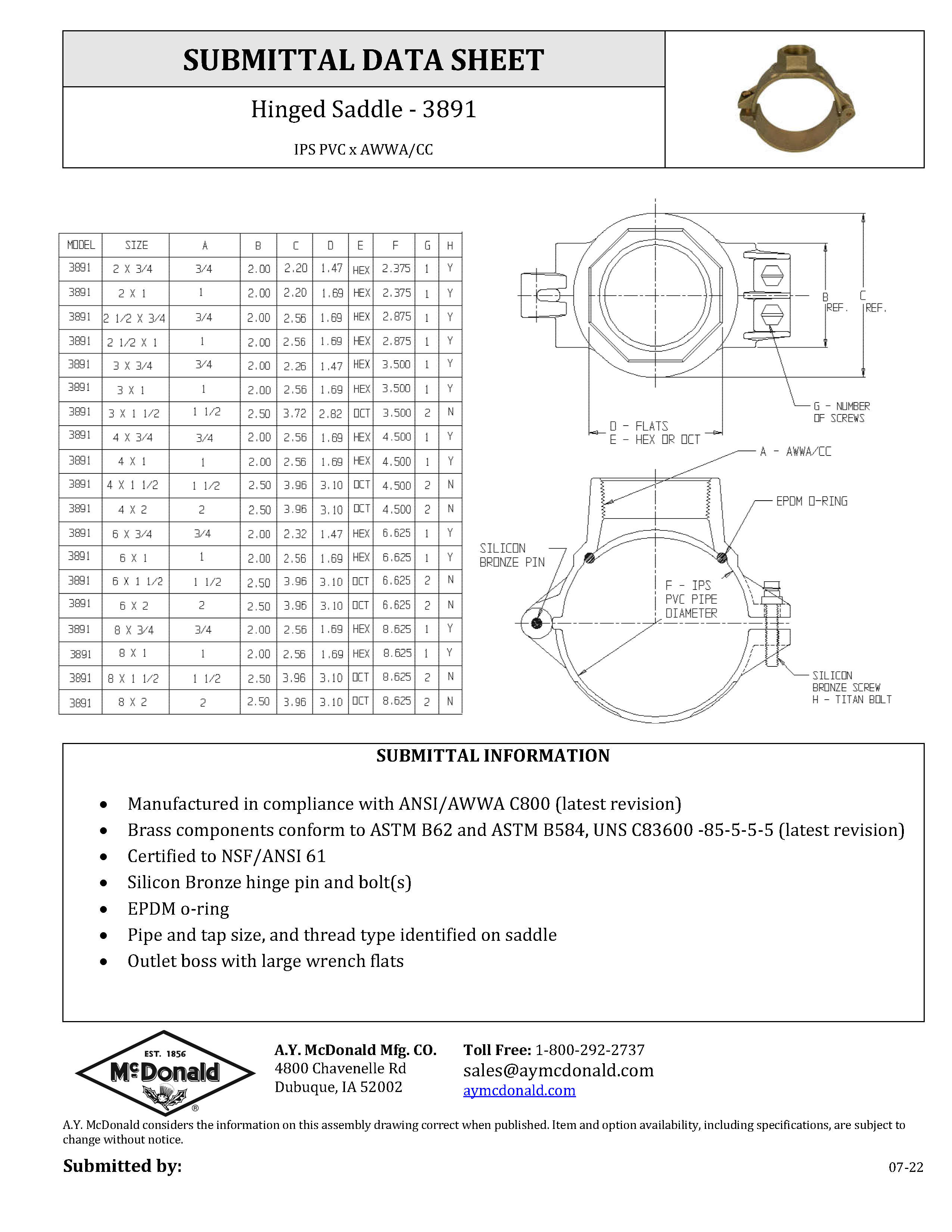
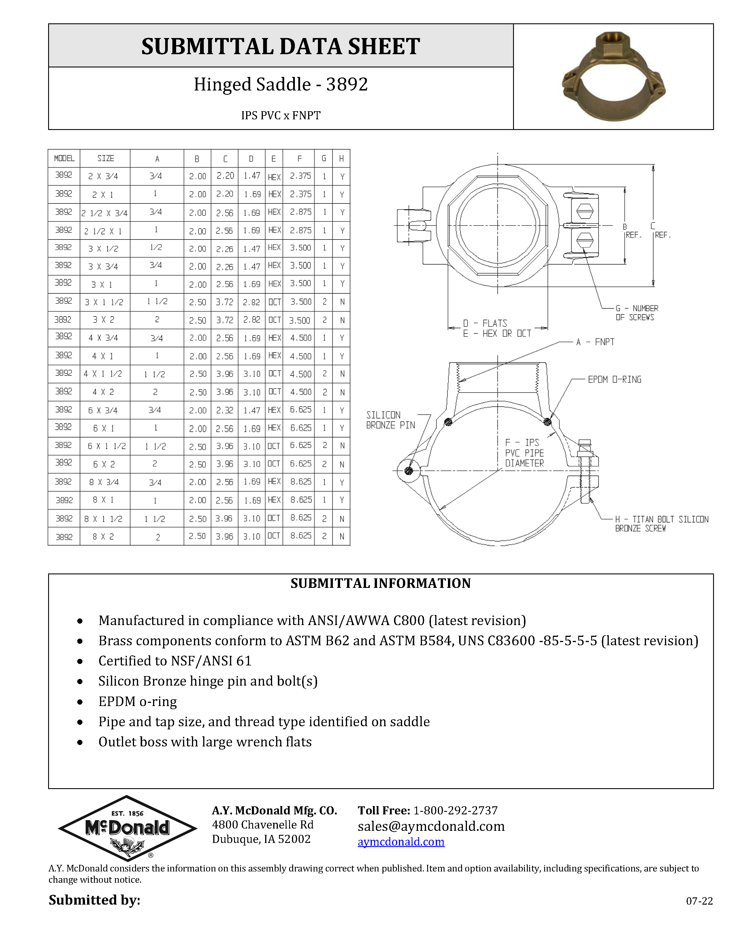
- Hinged Saddle, 3/22 - 3210-308
- Hinged Saddle, 9/22 - 3210-684
- Hinged Saddle Instructions, 1/23 - 3210-697
- Important Installation Notice, 3/22 - 3210-535
- Inline Dual Check Backflow Preventers/Device, 10/22 - 3210-348
- Inline Dual Check Backflow Preventers/Device, 3/22 - 3210-569
- Insert Stiffener Key, 11/22 - 3210-647
- Installation Instructions for Ball Valves, 3/22 - 3210-335
- Inverted Plug Curb Stops, 3/22 - 3210-331
- Longbox and Yokebox, 3/22 - 3210-316
- Loosely Assembled, 3/22 - 3210-345
- McGrip G & -3G Series - Compression Connectors, 3/22 - 3210-390
- McGrip G & -3G Series - Replacement Series Nut/Gasket, 3/22 - 3210-391
- McGrip ("GNS" & "-3GNS") Series Compression Connectors, 3/22 - 3210-607
- McGrip Series - Flare Threaded Compression Connectors, 3/22 - 3210-400
- McQuik Corp Q-16 Series - Compression Nut & Gasket Assembly (1 1/2" & 2" Replacement), 4/21 - 3210-364
- McQuik Q Series - Compression Connectors, 3/22 - 3210-315
- McQuik Q Series - Compression Gasket Assembly, 3/22 - 3210-329
- McQuik Q Series - Replacement Comp. Nut & Gasket, 3/22 - 3210-328
- McQuik ("Q") Corp-Threaded Series Compression Connectors, 4/21 - 3210-678
- Meter Coupling with Single & Dual Check Options, 3/22 - 3210-584
- Meter Setters Installation, 3/22 - 3210-358
- Meter Setter Installation Instructions, 11/19 - 3210-649
- Meter Valves & Couplings, 3/22 - 3210-179
- Mount Label - 3210-442
- No-Lead Wetted Parts, 2/15 - 3210-550
- Notice - Spacing Between Flanges, 3/22 - 3210-533
- P65 Warning Label - 3210-631
- PEP Handy-Loc ("-3H"), 3/22 - 3210-413
- PEP McQuik (-3Q-Series), 3/22 - 3210-346
- QC Series Compression Connectors, 9/15 - 3210-573
- Ranger Series Compression Connectors, 12/22 - 3210-629
- Repair Angle Ball Valve, 5/22 - 3210-692
- Repair Ball Valves, 1/17 - 3210-592
- Repair Clamps Installation Instructions, 3/22 - 3210-577
- Repair Procedure for Sampling Station Valve, 3/22 - 3210-559
- Replacement Flare Nut Adapter Ring, 3/22 - 3210-504
- Replacement Instructions for Handy Loc ("-3H") Series Compression Nut Assembly Installation, 3/22 - 3210-414
- Saddle - 2 Piece, 4/22 - 3210-327
- Saddle - Ductile Iron Steel Double Strap, 4/22 - 3210-380
- Saddle - Brass Double Strap, 4/22 - 3210-677
- Saddle - Bronze Double Strap, 3/22 - 3210-302
- Saddle - Bronze Single Strap, 4/22 - 3210-319
- Saddle - Ductile Iron Steel Single Strap, 4/22 - 3210-379
- Saddle - Stainless Steel Band, 4/22 - 3210-381
- Saddle - Stainless Steel Band, 4/22 - 3210-640
- Saddle - Stainless Steel Saddle, 5/20 - 3210-576
- Saddle - Stainless Steel Saddles w/Integral Valves 5/20 - 3210-641
- Saddle Sticker 4-5 ft-lbs, 1/18 - 3210-545
- Saddle Sticker 5-6 ft-lbs, 1/18 - 3210-539
- Saddle Sticker 7-9 ft-lbs., 1/18 - 3210-566
- Saddle Sticker 13-15 ft-lbs, 1/18 - 3210-546
- Saddle Sticker 17-19 ft-lbs, 1/18 - 3210-547
- Saddle Sticker 24-26 ft-lbs, 1/18 - 3210-548
- Sampling Procedures, Copper Meter Resetters w/Sampling Stations, 3/22 - 3210-595
- Small Wrap/Patch Repair Clamps, 4/22 - 3210-630
- Steam Applicants Only, 4/22 - 3210-429
- Stop & Drain Ball Valve - Direction of Flow, 3/22 - 3210-183
- Stop & Waste Ball Valves, 3/22 - 3210-337
- T PEP Series - Compression Connectors, 3/22 - 3210-300
- T Series - Compression Connectors, 3/22 - 3210-167
- Tapered Plug Curb Stop, 3/22 - 3210-332
- Telescoping Curb Box Installation, 3/22 - 3210-591
- Telescoping Curb Box Repair Instructions, 11/16 - 3210-593
- Telescoping Meter Flange, 1/18 - 3210-611
- Telescoping Meter Valve, 3/22 - 3210-644
- TITAN - Hinged Saddle Instructions, 9/22 - 3210-684
- Top Adjustable Meter Pit Kit, 4/22 - 3210-621
- UFR - 714U Series - Yoke Expander, 2/24 - 3210-422
- UFR - 7201 Series - Inline UFR, 2/24 - 3210-401
- UFR - 7202 Series - Angle Single UFR, 2/24 - 3210-430
- UFR - 7211 & 7214 Series - Inline Dual Check, 3/22 - 3210-426
- UFR - 7212 Series - Angle Dual Check, 3/22 - 3210-402
- Universal Cambridge Coupling, 3/22 - 3210-553
- Warning - Reclaimed Water ONLY, 4/22 - 3210-428
- Warning CA Label, 3/22 - 3210-405
- Warning CA, VT, MD, & LA Label, 8/11 - 3210-417
- Washer Kit 8403BW for use on HDPE SDR's 9-17 only, 3/22 - 3210-585
- Wire Inlet Tag, 3/22 - 3210-387
- Yoke Expander Single/Dual Check, 3/22 - 3210-580
- Yoke Expander Single/Dual Check, Reverse Flow 2/21 - 3210-671
- Yoke Expander Single/Dual Check w/Tamper Proof Screw Option, 3/22 - 3210-582
- Yoke Expander w/Tamper Proof Screw Option, 3/22 - 3210-581
Plumbing
- 2053T Installation & Maintenance, 10/21 - 3210-681
- 72600M Series (PRV) - No-Lead, 10/21 - 3210-679
- 72600T Series (PRV) - No-Lead, 10/21 - 3210-680
- Chicago Fittings X-Riser Detailed Installation Instructions, 8/23 - 3210-701
- Frostproof Sillcock Installation Instructions, 3/23 - 3210-682
- Low Pressure Gas Valves, 3/22 - 3210-340
- Supply Stop Instructions, 8/23 - 3210-702
- Threaded Ball Valves Installation Instructions, 9/23 - 3210-703
Pumps
- 1/3 HP Pump with 1/2 HP Motor Attached - 3210-272
- 1000 Series Vertical Multi-Stage Pump, 3/22 - 3210-153
- 1500 Series Horizontal Multi-Stage Pump, 3/22 - 3210-156
- 110911GRP, 110911GRPA, 110912GRP - 1 HP Grinder Pump, 2/21 - 3210-675
- 120912GRP, 120212GRP - 2 HP Grinder Pump, 2/21 - 3210-676
- 27000 Multi-Stage Booster Pump, 3/22 - 3210-371
- 404011EF/A, 404012EF/A, 405011EF/A, 405012EF/A - Sump Effluent Pumps, 2/21 - 3210-672
- 405011SJ/A/V, 405012SJ/A - Sump / Effluent / Sewage Pumps, 2/21 - 3210-673
- 405011EFS - 420012EFS, 405011SJX - 420012SJXH - Submersible Effluent & Sewage Pumps, 2/21 - 3210-674
- 6", 7", 8", & 10" Stainless Steel Submersible Pumps, 6/21 - 3210-637
- 8300 Series Jet Pumps, 3/22 - 3210-589
- 84000 Series Centrifugal Pumps, 3/22 - 3210-211
- 87000 Self-Priming Centrifugal Pump, 3/22 - 3210-351
- 8713 Series Float Valve Non-Potable Use Only, 9/22 - 3210-696
- 88000 Centrifugal Pumps, 6/11 - 3210-423
- 92000 Series Centrifugal Pumps, 3/22 - 3210-350
- Assembly Instructions - Booster Pump End w/Motor, 3/22 - 3210-406
- Attention Sticker - 3210-563
- AutoDRIVE Control Board Replacement, 2/22 - 3210-691
- AutoDRIVE Enclosure Front Cover Replacement, 2/22 - 3210-686
- AutoDRIVE Fan Kit Replacement, 2/22 - 3210-685
- AutoDRIVE Inverter Board Replacement, 2/22 - 3210-690
- AutoDRIVE Keypad Replacement, 2/22 - 3210-689
- AutoDRIVE Pressure Switch, 5/22 - 3210-688
- AutoDRIVE Transducer Control Wire, 2/22 - 3210-683
- AutoDRIVE Transducer Replacement, 5-22 - 3210-687
- AutoDRIVE Quick Start Guide, 12/21 - 3210-665
- AutoDRIVE Variable Frequency Drive Manual, 5/22 - 3210-669
- Convertible Jet Pumps, 4/22 - 3210-643
- Do Not Place Wrenches On The Plastic Valve Label, 10/14 - 3210-560
- DuraMAC - Quick Start Up Guide - Dual-Mode Commercial, 3/22 - 3210-490
- DuraMAC 17035R020P-1, 17052R020P-1, 17070R020P-2 - Centrifugal Pumps, 3/22 - 3210-467
- DuraMAC 17040, 17062, 17078C035P-2 Centrifugal Pumps, 3/22 - 3210-477
- DuraMAC 17044, 17060C070P-2 Centrifugal Pumps, 3/22 - 3210-486
- DuraMAC Battery Back-Up, 8/13 - 3210-468
- DuraMAC Dual-Mode Commercial Setup, 3/22 - 3210-491
- DuraMAC Effluent Pumps, 7/14 - 3210-420
- DuraMAC E-Series Booster Pump, 3/22 - 3210-602
- DuraMAC Expansion Tanks - 1 year, 9/11 - 3210-434
- DuraMAC Expansion Tanks - 5 year, 9/11 - 3210-435
- DuraMAC High Head Effluent Pump, 7/14 - 3210-492
- DuraMAC High Volume Sewage Pump, 7/18 - 3210-493
- DuraMAC Hydronic Tanks, 12/06 - 3210-436
- DuraMAC In-Line Pump Tanks, 9/11 - 3210-433
- DuraMAC Pedestal Sump Pumps, 8/13 - 3210-472
- DuraMAC Pump Tanks, 9/11 - 3210-432
- DuraMAC Repair Tee Assembly Instructions, 3/22 - 3210-596
- DuraMAC Sewage Pump Packages, 7/14 - 3210-475
- DuraMAC Sewage Pumps, 7/14 - 3210-421
- DuraMAC Submersible Sump Pumps, 1/15 - 3210-565
- DuraMAC Sump Pump Packages, 7/14 - 3210-474
- DuraMAC Sump Pumps, 6-16 - 3210-418
- DuraMAC Utility Pumps, 9/13 - 3210-419
- DuraMAC Variable Speed Boosters, 5/21 - 3210-552
- DuraMAC Variable Speed Boosters 1 1/2-3 HP, 2/20 - 3210-652
- DuraMAC Variable Speed Boosters Quick Start Guide, 3/22 - 3210-555
- DuraMAC Variable Speed Boosters Quick Start Guide, 3/20 - 3210-651
- DuraMAC Vertical Multi-Stage Centrifugal Pumps, 4/22 - 3210-528
- DuraMAC Water Pressure Booster - Dual-Mode Commercial, 4/22 - 3210-485
- DuraMAC Water Pressure Booster Pump Quick Start Guide, 3/22 - 3210-473
- DuraMAC Water Pressure Booster System (4-Lights) - Light Commerical & Irrigation, 4/22 - 3210-590
- DuraMAC Water Pressure Booster System (3-Lights) - Light Commerical & Irrigation, 4/22 - 3210-481
- DuraMAC Water Pressure Booster System - Residential (3-lights), 4/22 - 3210-444
- DuraMAC Water Pressure Booster System - Residential (4-lights), 3/22 - 3210-586
- E Series Quick Start Guide, 4/22 - 3210-603
- Guardian - Radon Ready Instruction Sheet, 3/22 - 3210-564
- Guardian - Radon Ready, 3/22 - 3210-377
- Guardian Household Booklet, 3/22 - 3210-407
- Guardian Installation, 12/21 - 3210-352
- Guardian Instruction Sheet, 3/22 - 3210-536
- Guardian Pump Warning, 3/22 - 3210-375
- Guardian Sticker, 3/12 - 3210-354
- Guardian Sticker - 3210-362
- Guardian Sticker, 3/18 - 3210-551
- Guardian Valve Label, 3/22 - 3210-356
- Guardian Valve Label, 3/22 - 3210-369
- Installation & Operation Manual for Submersible Sump Pump, 4/17 - 3210-601
- Jet Kit, 12/22 - 3210-612
- Jet Pump Repair Kits, 3/22 - 3210-366
- Jet Pumps, 3/22 - 3210-184
- McDonald Bottom Suction Cistern Pump, 3/22 - 3210-549
- McDonald Submersible Pumps Installation Instructions, 3/22 - 3210-324
- Model 303022SP Service & Operating Manual, 4/22 - 3210-499
- Motor Wired for 460V - 3210-554
- Pressure Relief Valves 3/22 - 3210-370
- Pump Control with Thermally Protected Motors, 3/22 - 3210-466
- Remove at Installation - 3210-489
- Sprinkler Pumps, 3/22 - 3210-598
- Stainless Steel Submersible Pump Assembly Guide for 90 GPM Pumps w/ 4" Motor, 6/20 - 3210-654
- Stainless Steel Submersible Pump Assembly Guide for 90 GPM Pumps w/ 6" Motor, 6/20 - 3210-655
- Stainless Steel Submersible Pump Assembly Guide for 150 GPM Pumps w/ 4" Motor, 6/20 - 3210-656
- Stainless Steel Submersible Pump Assembly Guide for 150 GPM Pumps w/ 6" Motor, 6/20 - 3210-657
- Stainless Steel Submersible Pump Assembly Guide for 230/300 GPM Pumps w/ 4" Motor, 6/20 - 3210-658
- Stainless Steel Submersible Pump Assembly Guide for 230/300 GPM Pumps w/ 6" Motor, 6/20 - 3210-659
- Stainless Steel Submersible Pump Assembly Guide for 400/500 GPM Pumps w/ 6" Motor, 6/20 - 3210-660
- Stainless Steel Submersible Pump Assembly Guide for 400/500 GPM Pumps w/ 8" Motor, 6/20 - 3210-661
- Stainless Steel Submersible Pump Assembly Guide for 650/800 GPM Pumps w/ 8" Motor, 6/20 - 3210-662
- Stainless Steel Submersible Pump Assembly Guide for 1100 GPM Pumps w/ 8" Motor, 6/20 - 3210-663
- Submersible Pumps, 2/21 - 3210-636
- Troubleshooting Yaskawa Drives - 3210-561
Natural Gas Products
- 4819-004 HPNPT PBK Quick Thread Adapter, 4/22 - 3210-623
- 555 Angle Gas Valve, 3/22 - 3210-318
- 558 Natural Gas Relubrication Tool, 3/22 - 3210-301
- 6282 Natural Gas By-Pass Procedure, 3/22 - 3210-625
- 6312 Natural Gas Manifold Bypass Meter Bar, 3/22 - 3210-383
- 6410 Natural Gas Bypass Meter Bar, 3/22 - 3210-382
- 6480 Natural Gas Industrial Bypass Meter Bar, 5/21 - 3210-538
- 6758 Natural Gas Meter Bar, 3/22 - 3210-312
- Heads Up Label, 7/22 - 3210-694
- Low Pressure Natural Gas Valves, 3/22 - 3210-340
- Natural Gas Angle Ball Valve, 3/23 - 3210-389
- Natural Gas - 3/4" & 1" Inline Bypass Valve Procedure, 12/23 - 3210-635
- Natural Gas Ball Valve, 3/22 - 3210-294
- Natural Gas Inline Bypass Ball Valves, 12/23 - 3210-700
- Natural Gas Meter Bar, 3/22 - 3210-295
- Natural Gas Unions-3 Piece, 3/22 - 3210-292
- Natural Gas Valves-Plug, 3/19 - 3210-336
- Natural Gas Portable Bypass Kit, 4/22 - 3210-622
- Regulating Hose Kit Instructions, 3/23 - 3210-653
- Relubrication Instructions 6722 Natural Gas Meter Bar, 2/22 - 3210-304
Innovation
Booster Pumps
A.Y. Boosters
Meet the world's most intelligent, yet simple boosting system. Designed to meet virtually all boosting applications – there's a model for your specific needs. Click on the model name below to learn more.
Residential
The residential booster can be run in three different modes, based on your boosting needs. In Pressure Mode, the pump starts with pressure drop and stops on low flow. In Flow Mode, the pump starts and stops by sensing flow. In Conservation Mode, the pump only operates during a peak demand, such as when multiple showers, bathtubs, or irrigation systems are running.
Instruction Manual 3 Light Prior to 1-17
Instruction Manual 4 Light After 1-17
E-Series
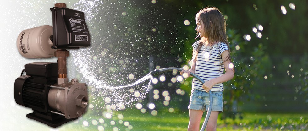
A.Y. McDonald’s E-Series DuraMAC™ Water Pressure Booster System is ideal for residential, irrigation, or light commercial applications. This pump comes complete with easy set-up instructions, all metal connections, a half-gallon pressure tank, and the inclusion of a check valve. In addition, experience a quiet operation due to the TEFC single phase motor, along with extra security because the electronics are separated and sealed from the waterway. Designed to shut off when no flow is detected, the E-Series DuraMAC™ Water Pressure Booster System gives that extra boost that you (and your water pressure) have been waiting for!
Light Commercial
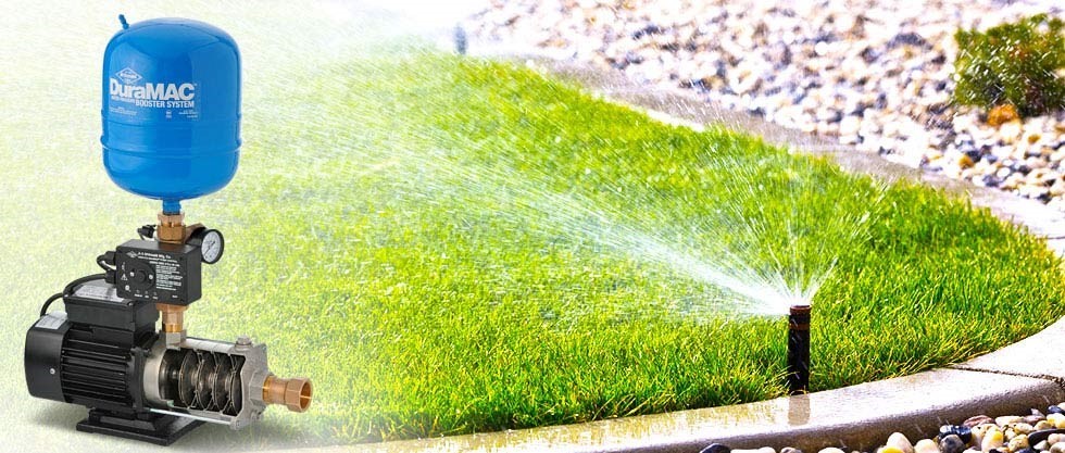
The light commercial / irrigation boosters can be run in three different modes, based on your boosting needs. In Pressure Mode, the pump starts with pressure drop and stops on low flow. In Flow Mode, the pump starts and stops by sensing flow. In Conservation Mode, the pump only operates during a peak demand, such as when multiple showers, bathtubs, or irrigation systems are running.
Installation Instructions 3 Light Prior to 1-17
Installation Instructions 4 Light After 1-17
Commercial
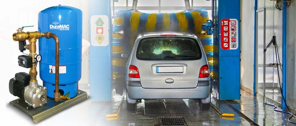
The commercial booster may be run in Pressure Mode, where the pump starts with pressure drop and stops on low flow. It may also be run in a conventional Pressure Switch Mode, where the pump starts and stops on pressure.
Industrial
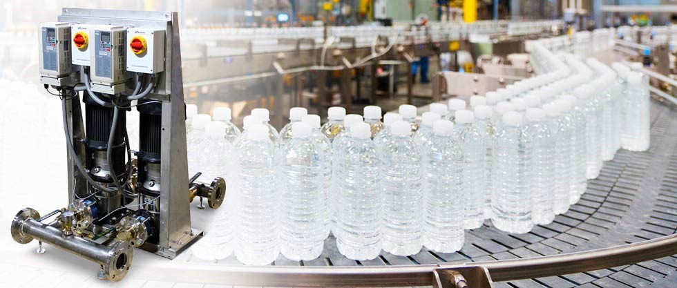
A.Y. McDonald’s new DuraMAC Variable Speed Booster is a stainless steel pump that adjusts its speed based on the demand of the system, maintains a constant pressure, and is easy to install. The motor provides quiet operation, at optimal working capacity. Click on the information below to learn more about the most intelligent, yet simple, pressure boosting system on the market.
Installation Instructions (1.5 - 3 HP) 2-20, 3210-652 - 2/20
Installation Instructions (3 - 10 HP) 3-18, 3210-552 - 3/18
Quick Start Guide (1.5 - 3 HP) 3-20, 3210-651 - 3/20
Quick Start Guide (3 - 10 HP) 3-18, 3210-555 - 3/18
Submittals Dropdown (1.5-3 HP)5-20
Submittals Dropdown (3-10 HP)8-14
Logos
A.Y. McDonald Logos
Click on the images below to view them full size. To download, right click and choose "Save Image As".
Product Certifications
Titan Bolt
TITAN
No-Lead Experts
Trust in the No-Lead Experts
No-Lead Brass
In January 2011, the Reduction of Lead in Drinking Water Act was signed into law, which reduced the allowable lead content of wetted surfaces in drinking water pipes, pipe fittings, and plumbing fixtures as of January 4, 2014. To ensure our customers bottom lines weren't impacted negatively by this transition to no-lead brass, A.Y. McDonald Mfg. Co. launched a microsite with the reference materials below. Although this full site is no longer necessary, we remain committed to educating and assisting our customers. For this reason, we are providing the reference materials and resources regarding the no-lead legislation and transition below. For further information, please contact your sales representative or our factory at 1-800-292-2737.
Water Pumps
EPA Lead water in Drinking Water FAQs - 12/2013
Important No-Lead Letter - 09/2013
Leaded Brass Disclaimer - 06/2011
No-Lead The Engineering Basics - 09/11
Read the California Health and Safety No-Lead Legislation
Read the California No-Lead Legislation
Read the Louisiana No-Lead Legislation
Read the Maryland No-Lead Legislation
Read the Maryland No-Lead Legislation FAQ
Read the Vermont No-Lead Legislation - 11/10
Read the Vermont No-Lead Legislation FAQ
Technical Specifications - 02/13
Vermont's Attorney General on Enforcing VT Act 193 - 11/09
Plumbing Supplies
EPA Lead in Drinking Water FAQs 12/13
Important No-Lead Letter - 09/13
Leaded Brass Disclaimer - 6/11
Read the California Health and Safety No-Lead LegislationRead the California No-Lead Legislation
Read the Louisiana No-Lead Legislation
Read the Maryland No-Lead Legislation - 13/12
Read the Maryland No-Lead Legislation FAQ
Read the Vermont No-Lead Legislation - 11/10
Read the Vermont No-Lead Legislation FAQ
Vermont's Attorney General on Enforcing VT Act 193
Water Service
EPA Lead in Drinking Water FAQs - 12/13
Important No-Lead Dates Letter - 10/2012
Important No-Lead Letter - 09/2013
Lead vs No-Lead Packaging - 09/11
Lead vs No-Lead Packaging - 04/12
Read the California Health and Safety No-Lead Legislation
Read the California No-Lead Legislation
Read the Louisiana No-Lead Legislation
Read the Maryland No-Lead Legislation - 13/12
Read the Maryland No-Lead Legislation FAQ
Read the Vermont No-Lead Legislation - 11/10
Read the Vermont No-Lead Legislation FAQ
UFR
THE PROBLEM: NON-REVENUE WATER
Every water system has to cope with non-revenue water. Main leaks, theft, tank overflows and unmeasured flow through water meters all contribute to a system's non-revenue water problem. According to the American Water Works Association (AWWA), 14% of indoor household usage in North America can be attributed to leaks. As residential water meters aren't designed to register low-flows such as leaks and drips, much of this usage goes un-metered and un-billed. This type of non-revenue water is called "apparent loss" and is valued at the retail water rate. For systems in which waste water is also billed based on water consumption, this apparent loss is valued at the retail rate for water and waste water combined. Apparent losses through residential water meters can add up to millions of dollars annually in non-revenue water and sewer.
THE SOLUTION: UNMEASURED-FLOW REDUCER (UFR)
The UFR captures this low-flow water and forces it through the meter in a way that causes nearly every drop to be registered. Apparent losses are reduced and customers are held accountable for their actual usage.
HOW THE UFR WORKS
The UFR works by changing the way water flows through the meter at low flow rates. At low flow rates there is not enough energy in the flow to activate the water meter. With the UFR installed, the low, linear flows are divided into batches that are forced through the meter at a higher flow rate. These higher flows can now be registered by the water meter, reducing apparent losses and increasing revenue.
At normal household flow rates, the UFR is fully open, allowing water to flow normally with minimal head loss. As flow is reduced, the UFR returns to its operation of batching the water flow.
THE RESULTS
UFR installations can increase the measurement of billable water between as much as five and ten percent. Customers are held accountable for their actual usage and the system's apparent losses are reduced considerably. Customers that are held accountable for their usage are more likely to fix leaks and conserve our most precious resource, clean water.
Product Literature
- UFR Print Catalog Section (PDF)
- UFR Meter Setter and Resetter Model Number Adders
- UFR Marketing White Paper
Tools
- UFR Revenue Calculator (PDF)
- UFR Sample Specification (PDF)
- UFR Sample Specification (WORD)
- UFR Comparison Pilot Guidelines (PDF)
- UFR Call Report (EXCEL)
Technical Papers, Articles and Links
- Unmeasured-Flow Reducer (UFR) Testing
- City of Dubuque - "Smart Metering" Leak Detection System
- Watts Bar Utility District UFR Testimonial (PDF)
- IBM Research - Smart Water Pilot Study - Dubuque (PDF)
- Average Indoor Water Use Report (PDF)
- Trials to Quantify and Reduce in-situ Meter Under-Registration (PDF)
- Reduction of Apparent losses Using the UFR-Foreign Case Studies (PDF)
- IBM Sets Out to Make a City in Iowa 'Smarter' - New York Times
- AWWA Water Loss Control Website
- Testing the UFR on Test Benches (PDF)
Meter Set Assembly
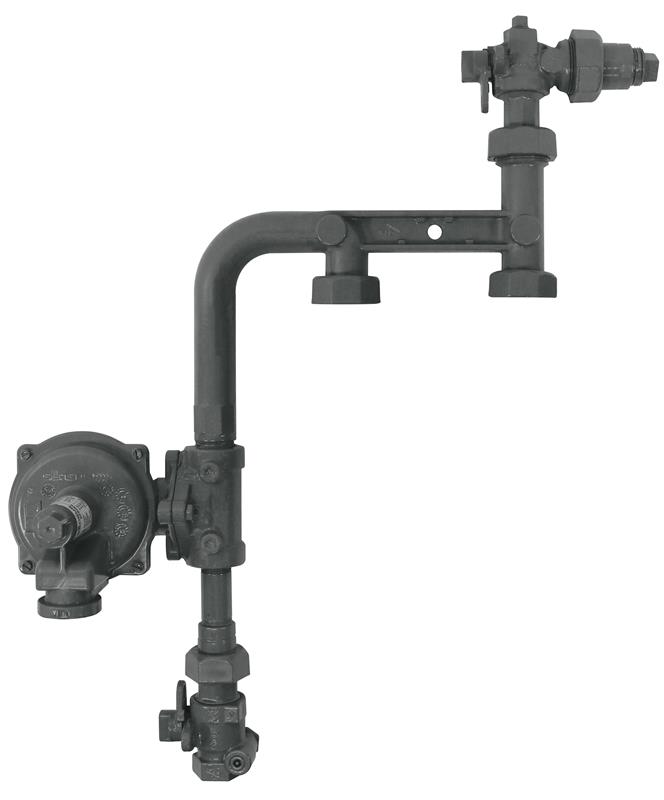
THE NATURAL GAS
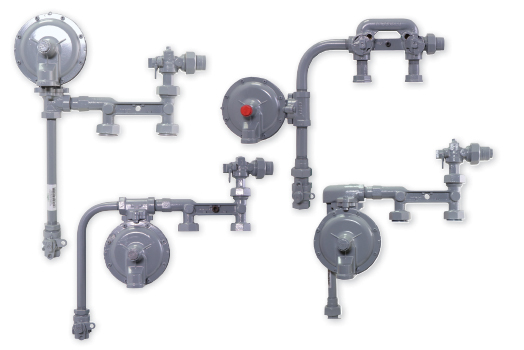
METER SET ASSEMBLY
You Spoke. We Listened.
Demand in the Market
Customer Focused
- Quality meter set assemblies
- Pressure testing for safety and quality
- Top notch customer service
- All parts under one roof - except regulator
- Traceability
Pressure Testing
- The regulator is pressurized to ensure it is the correct regulator and is set properly.
*Not a flowing set point per regulator specification
- The inlet of the meter set assembly is pressurized according to the customer’s
required specification so leaks can be detected.
*We do detect lockup – not at designated pressure
- Joints after the regulator are tested to ensure all joints seal well.
- The outlet side of the meter set assembly is tested at about 40 psi.
Robotic Painting
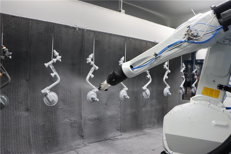
A brand new paint line was installed to coat the meter set assemblies. The focus for this new paint line is efficiency, quality paint output, and taking into account the vast volume of meter set assemblies that can be completed.
- Paint Specifications (relates to color and gloss, not to material (paint)):
- Fabrication Paint - 2-part epoxy primer applied by eletrostatic air spray, ANSI 49 gray 2-part Urethane topcoat applied by electrostatic air spray, Approximately 6-10mil total DFT (dry film thickness).
- The paint chosen provides excellent corrosion resistance and durability for this application. Salt spray tests have been performed in order to ensure the protection is acceptable. The paint, along with an efficient process, provides a quality meter set assembly.
- Coating Test Documents
- Salt Spray Test per ASTM B117, measuring failure at 4% rust
- Cleaning specification
- Pipe will be free of chips and debris using a solvent wash per SSPC-SP1 standards
- Protection in paint process (masking, etc.)
- Threads and open ends will be plugged or capped to prevent any paint entering the meter set assembly
- Custom masks will be applied for tags and other areas that need to remain unpainted

